Centrifugal pumps are widely used across Australian mining, civil construction, water management, chemical handling and industrial fluid-transfer applications. Their ability to deliver high flow rates with relatively simple mechanical construction makes them well suited to demanding environments.
However, pump reliability depends on more than selecting a pump with the required flow rate. The pump must be correctly sized for the system, matched to the fluid, installed correctly and protected from conditions such as cavitation, dry running, excessive solids, corrosion and suction restrictions.
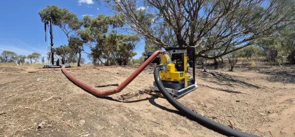
For Australian industrial sites, particularly remote mining and civil projects, the right approach is to design the complete liquid management system rather than treating the pump as an isolated component.
This guide explains how centrifugal pumps work, how to select the correct pump, how to calculate flow and head requirements, how to prevent common failures, and how Liquimech approaches complete pump and liquid management systems.
Key Takeaways
- Centrifugal pumps are well suited to high-flow applications involving water and other relatively low-viscosity liquids.
- Pump selection must consider flow rate, total dynamic head, fluid properties, temperature, solids content, suction conditions, duty cycle and power availability.
- The impeller, casing, mechanical seal and shaft assembly all influence pump performance and service life.
- Correct Net Positive Suction Head Available (NPSHa) is essential for preventing cavitation.
- Operating close to the pump’s Best Efficiency Point (BEP) generally reduces hydraulic and mechanical stress.
- Open, semi-open and closed impellers suit different fluid and solids-handling requirements.
- Suction piping, strainers, footvalves and priming arrangements can have a major impact on pump reliability.
- Remote Australian sites require equipment designed around serviceability, environmental conditions and access to maintenance.
- A complete liquid management system should consider the pump, storage, piping, valves, controls and protection equipment together.
- Liquimech designs engineered liquid management solutions for demanding Australian mining, civil and industrial applications.
What Is a Centrifugal Pump?
A centrifugal pump is a mechanical device that converts rotational energy from a motor or engine into hydraulic energy to move liquid.
The rotating component, called an impeller, accelerates liquid from the centre of the impeller toward its outer diameter. The pump casing then converts part of that velocity into pressure, allowing the liquid to move through the discharge pipework.
Unlike positive displacement pumps, centrifugal pumps do not move a fixed volume of liquid with every revolution. Their flow rate changes according to the relationship between the pump and the system in which it operates.
This makes centrifugal pumps particularly effective where the application requires:
- High or continuous flow rates
- Relatively low-viscosity liquids
- Steady fluid transfer
- Dewatering
- Tank and storage transfer
- Water truck filling
- Dust suppression
- Process water circulation
- Industrial water transfer
- Certain chemical transfer applications
The correct pump depends on the entire hydraulic system, not simply the desired flow rate.
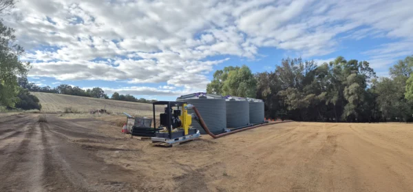
How Does a Centrifugal Pump Work?
The operating principle is straightforward.
Liquid enters the pump through the suction connection and reaches the centre, or eye, of the impeller. As the impeller rotates, its blades transfer energy to the liquid and accelerate it outward.
This creates a lower-pressure region near the impeller eye, allowing liquid to enter the pump when sufficient suction pressure is available.
The liquid then enters the casing, where the flow area increases and some of the liquid’s velocity is converted into pressure. The pressurised liquid leaves through the discharge connection and travels through the downstream pipework.
A centrifugal pump therefore does not literally “suck” liquid from a tank. It creates the pressure conditions required for liquid to flow into the pump.
This distinction is important when designing suction systems because the available suction pressure determines whether the pump can operate without cavitation.
Main Components of a Centrifugal Pump
Although centrifugal pumps are relatively simple machines, each major component has an important engineering function.
Impeller
The impeller transfers rotational energy to the liquid.
Impeller design affects:
- Flow rate
- Head
- Hydraulic efficiency
- Solids handling
- Wear resistance
- Power requirements
Impellers are available in different configurations and materials depending on the application.
Pump Casing
The casing contains the rotating impeller and directs liquid toward the discharge connection.
A volute casing gradually increases the flow area around the impeller. This helps convert velocity into pressure.
The casing material must be compatible with the pumped liquid and the operating environment.
Shaft
The shaft transfers mechanical power from the motor or engine to the impeller.
Correct alignment is critical. Shaft misalignment can increase vibration and accelerate bearing, seal and coupling wear.
Mechanical Seal
The mechanical seal prevents liquid from escaping along the rotating shaft.
Seal selection depends on factors such as:
- Fluid chemistry
- Temperature
- Pressure
- Solids concentration
- Abrasiveness
- Pump speed
- Operating conditions
A seal designed for clean water may not be appropriate for abrasive slurry or aggressive chemicals.
Bearings
Bearings support the rotating shaft and maintain the required position of the rotating assembly.
Poor lubrication, misalignment, excessive vibration or hydraulic loads can shorten bearing life.
Centrifugal Pump vs Positive Displacement Pump
The choice between a centrifugal pump and a positive displacement pump depends on the application.
Centrifugal pumps are generally suited to:
- High-flow water transfer
- Continuous pumping
- Low-viscosity liquids
- Dewatering
- Tank filling
- Process water
- General industrial fluid transfer
Positive displacement pumps may be more suitable for:
- Highly viscous liquids
- Applications requiring controlled displacement
- High-pressure, lower-flow duties
- Fluids where maintaining flow independent of pressure is important
Neither pump type is universally better. The correct choice depends on the fluid, flow, pressure, operating cycle and system design.
Understanding Pump Head and Flow
Two of the most important pump selection parameters are flow rate and head.
Flow Rate
Flow rate describes how much liquid the system must move over a given period.
It may be expressed in:
- Litres per minute (L/min)
- Litres per second (L/s)
- Cubic metres per hour (m³/h)
- Cubic metres per second (m³/s)
For example, if a 25,000-litre water truck needs to be filled in five minutes:
Required average flow = 25,000 ÷ 5 = 5,000 L/min
This is only the starting point. The pump must also provide enough head to overcome the complete hydraulic resistance of the system.
Pump Head
Pump head represents the energy the pump adds to the liquid and is commonly expressed in metres of liquid.
The required pump head can include:
- Static elevation
- Pressure requirements
- Pipe friction
- Hose friction
- Valve losses
- Strainer losses
- Footvalve losses
- Fittings and bends
- Standpipe resistance
- Other system components
Selecting a pump based only on flow rate can therefore result in poor performance.
What Is Total Dynamic Head?
Total Dynamic Head (TDH) is the total head the pump must provide at the required operating flow.
A simplified system calculation considers:
TDH = Static Head + Pressure Head + Friction Losses
The actual calculation depends on the configuration of the system.
Friction losses increase as flow increases. Pipe diameter also has a major effect. A smaller pipe can create substantially higher friction losses, increasing the head required from the pump.
This is why pump selection should occur after the hydraulic system has been properly defined.
Understanding NPSH and Cavitation
Net Positive Suction Head is one of the most important considerations when selecting and installing a centrifugal pump.
There are two key values:
- NPSHa — Net Positive Suction Head Available: determined by the actual system and operating conditions.
- NPSHr — Net Positive Suction Head Required: the minimum suction condition required by the pump for a specified operating point.
The available NPSH must provide an adequate margin above the pump’s required NPSH.
What Causes Cavitation?
Cavitation occurs when local pressure within the pump falls sufficiently for vapour bubbles to form. These bubbles can subsequently collapse as pressure increases.
Repeated cavitation can cause:
- Impeller pitting
- Noise
- Vibration
- Reduced hydraulic performance
- Seal damage
- Bearing damage
- Accelerated component wear
A pump experiencing cavitation can sound as though gravel is moving through the casing.
How to Reduce Cavitation Risk
Potential measures include:
- Increasing the liquid level above the pump
- Reducing suction pipe friction
- Increasing suction pipe diameter
- Removing unnecessary suction bends
- Cleaning blocked strainers
- Reducing excessive pump speed
- Reducing liquid temperature where appropriate
- Reducing flow if the system permits
- Selecting a pump with suitable NPSH characteristics
NPSH should be checked during the design stage rather than treated as a commissioning problem.
Understanding the Pump Performance Curve
Every centrifugal pump has a performance curve showing how the pump behaves at different operating conditions.
The curve commonly relates:
- Flow rate
- Pump head
- Efficiency
- Power
- NPSH requirements
The actual operating point occurs where the pump curve intersects the system curve.
This means the pump does not operate at an arbitrary flow rate. The final flow is determined by the interaction between the pump and the complete hydraulic system.
What Is the Best Efficiency Point?
The Best Efficiency Point (BEP) is the region where the pump operates most efficiently.
Operating significantly away from BEP can increase:
- Hydraulic recirculation
- Vibration
- Radial loads
- Bearing loads
- Seal stress
- Energy consumption
- Component wear

How to Select the Right Centrifugal Pump
Correct pump selection starts with defining the application.
Before selecting a pump, establish:
- Required flow rate
- Required total head
- Fluid type
- Fluid temperature
- Fluid viscosity
- Fluid density
- Solids concentration
- Solids size and abrasiveness
- Chemical compatibility
- Suction conditions
- Operating hours
- Available power
- Environmental conditions
- Installation configuration
- Required control system
- Maintenance and access requirements
A pump specification that only states “X litres per minute” is incomplete.
Electric vs Diesel-Driven Centrifugal Pumps
Power availability is particularly important on Australian worksites.
Electric drive
Electric motors can be an effective option where reliable electrical infrastructure is available.
Advantages can include:
- Simple operation
- Low routine maintenance
- Reliable continuous operation
- Straightforward integration with control systems
- Suitable for fixed installations
Diesel drive
Diesel-driven pump systems can be advantageous for remote or mobile applications where electrical infrastructure is unavailable or impractical.
They can provide:
- Independent operation
- Mobility
- Flexible deployment
- Suitable power for remote dewatering
- Operation away from fixed electrical infrastructure
The choice should consider the site’s operating conditions, fuel requirements, noise, emissions, maintenance requirements and available infrastructure.
Choosing Pump Materials
Material selection is critical in industrial applications.
The correct material depends on the fluid and operating conditions.
Important factors include:
- Corrosion
- Abrasion
- Temperature
- Chemical concentration
- pH
- Solids content
- Fluid velocity
- Operating pressure
Cast materials may be appropriate for many clean-water applications, while stainless steels, specialised alloys, coatings or engineered polymers may be more appropriate for corrosive or chemically aggressive fluids.
For abrasive mining applications, wear-resistant materials may be required for the impeller, casing and other wetted components.
Material compatibility should always be confirmed against the actual fluid rather than assumed from the application name.
Open vs Closed Impellers
Impeller configuration is particularly important when handling solids.
Closed Impellers
Closed impellers have shrouds surrounding the vanes.
They can provide high hydraulic efficiency and are often suitable for relatively clean liquids.
Typical applications include:
- Clean water
- Tank transfer
- High-flow water systems
- Industrial process water
However, they can be more susceptible to blockage when the pumped liquid contains larger debris or fibrous material.
Open Impellers
Open impellers have exposed vanes and are generally better suited to applications where solids handling is important.
They may be used for:
- Dewatering
- Construction water
- Mining water
- Liquids containing suspended solids
- Applications where blockage resistance is important
The trade-off is that open impellers may have lower hydraulic efficiency and can require closer attention to wear and operating clearances.
Pumping Abrasive Water and Slurries
Mining environments can expose pumps to sand, silt, rock particles and other abrasive materials.
A pump handling abrasive liquid should be selected around the actual solids characteristics.
Consider:
- Solids concentration
- Particle size
- Particle shape
- Abrasiveness
- Specific gravity
- Required flow rate
- Operating hours
- Expected wear rate
Simply selecting a larger pump does not solve an abrasion problem.
The impeller, casing and other wetted components must be selected to withstand the actual service conditions.
Where appropriate, wear-resistant materials and coatings can extend component life and reduce maintenance frequency.
Chemical Compatibility
Chemical transfer requires careful selection of all wetted components.
Compatibility should be checked for:
- Pump casing
- Impeller
- Mechanical seal
- O-rings
- Gaskets
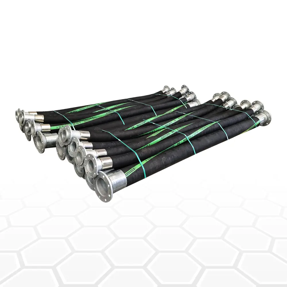
- Hoses
- Valves
- Strainers
- Footvalves
- Pipework
Important chemical parameters include concentration, temperature and exposure time.
A component that is compatible with a dilute chemical may not be suitable at higher concentrations or temperatures.
For hazardous or environmentally sensitive liquids, pump selection should also consider containment, leak detection, flushing arrangements and applicable site and regulatory requirements.
Suction Piping Design
Many centrifugal pump problems originate on the suction side.
The suction system should be designed to provide stable flow into the pump with minimal pressure loss.
Good practice commonly includes:
- Using an appropriately sized suction pipe
- Minimising unnecessary bends and fittings
- Avoiding sharp changes in flow direction immediately before the pump
- Keeping suction lines as short and direct as practical
- Preventing air leaks
- Supporting pipework independently of the pump
- Maintaining adequate liquid level
- Selecting strainers with appropriate open area
- Checking suction losses during system design
The exact suction arrangement depends on the pump and application. A generic rule should never replace a proper hydraulic assessment.
Footvalves and Strainers
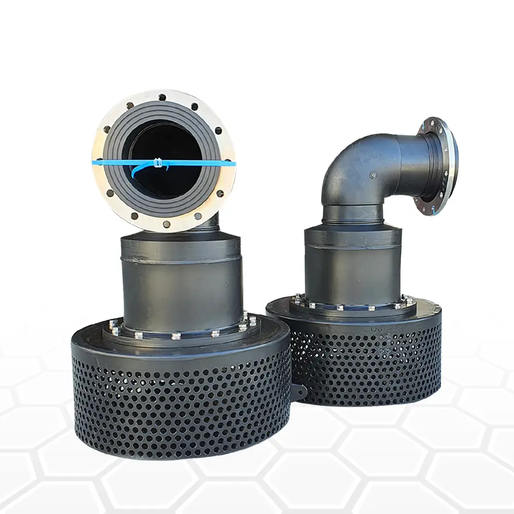
Footvalves and strainers are important components in many centrifugal pump installations, particularly where the pump is positioned above the liquid source.
Footvalves
A footvalve can help maintain liquid in the suction line and support priming.
A correctly selected footvalve should:
- Provide adequate flow area
- Minimise pressure loss
- Resist the site’s fluid and environmental conditions
- Prevent excessive backflow
- Be accessible for inspection and maintenance
Strainers
Strainers protect the pump from unwanted debris.
However, a strainer that is too restrictive can create excessive suction losses and increase cavitation risk.
Strainer selection therefore requires a balance between:
Protection + Flow Area + Pressure Loss + Maintenance Requirements
Liquimech designs heavy-duty footvalve and strainer solutions for demanding mining, civil and industrial environments where reliability and serviceability are critical.
Pump Priming and Dry Running
A standard centrifugal pump generally needs the pump casing and suction arrangement to be correctly primed before operation.
Running a conventional centrifugal pump without sufficient liquid can damage the mechanical seal and other components.
Before starting the pump, confirm:
- The pump casing is properly filled
- The suction line is correctly primed
- The footvalve is functioning where fitted
- Suction valves are open
- The discharge system is configured correctly
- The mechanical seal has the required operating conditions
- The pump is not expected to run dry
Where frequent air entry or interrupted supply is expected, a self-priming pump or another suitable system configuration may be more appropriate.

How to Install a Centrifugal Pump Correctly
Correct installation has a direct impact on pump life.
1. Provide a Rigid Foundation
The pump and driver should be installed on a rigid, stable foundation capable of supporting the equipment without excessive movement.
The base should be appropriately levelled and secured.
2. Align the Pump and Driver
Pump and motor shaft alignment is critical.
Poor alignment can cause:
- Vibration
- Bearing failure
- Coupling wear
- Seal failure
- Shaft damage
Alignment should be checked using an appropriate precision alignment method and verified after installation and pipework connection.
3. Support the Pipework
Pump connections should not be used to support the weight of the pipework.
Pipework loads transferred into the pump can cause distortion, misalignment and premature failure.
4. Check Suction Conditions
Confirm that the suction pipework, valves and strainers provide the required flow without excessive restriction.
5. Verify Rotation
The motor or driver rotation must match the pump’s required direction.
Incorrect rotation can result in poor performance or mechanical damage.
Centrifugal Pump Commissioning Checklist
A controlled commissioning process reduces the risk of avoidable failures.
Before starting
- Confirm pump and motor installation.
- Check shaft and coupling alignment.
- Verify lubrication.
- Confirm all guards are installed.
- Check suction and discharge valve positions.
- Confirm the pump is correctly primed.
- Inspect strainers and footvalves.
- Verify electrical connections or engine installation.
- Confirm rotation direction.
- Check instrumentation.
During startup
Monitor:
- Discharge pressure
- Flow rate
- Motor current or engine load
- Pump vibration
- Bearing temperature
- Mechanical seal condition
- Unusual noise
- Suction pressure where instrumentation is available
Compare operating conditions with the pump’s design duty and performance curve.
After startup
Record the initial operating data.
A commissioning baseline makes future fault diagnosis easier. Changes in pressure, current, vibration, temperature or flow can provide early warning of developing problems.
Common Centrifugal Pump Problems
Pump Will Not Prime
Possible causes include:
- Air entering the suction line
- Insufficient liquid level
- Faulty footvalve
- Leaking suction connections
- Incorrect priming procedure
- Excessive suction lift
- Blocked or incorrectly configured suction equipment
The entire suction system should be checked rather than replacing the pump immediately.
Low Flow Rate
Possible causes include:
- Incorrect pump selection
- Excessive system resistance
- Blocked suction strainer
- Worn impeller
- Incorrect rotation
- Air entering the suction line
- Excessive pipe friction
- Operating outside the intended pump curve
Excessive Vibration
Common causes include:
- Misalignment
- Cavitation
- Unbalanced rotating components
- Bearing problems
- Pipework loads
- Foundation problems
- Operating too far from the preferred operating region
- Hydraulic instability
Vibration should be investigated rather than treated as normal pump behaviour.
Mechanical Seal Failure
Potential causes include:
- Dry running
- Excessive temperature
- Incorrect seal selection
- Shaft misalignment
- Excessive vibration
- Abrasive solids
- Incorrect installation
- Poor operating conditions
Repeated seal failures usually indicate an underlying system or operating problem.
What Happens When a Pump Runs Against a Closed Discharge Valve?
Operating a centrifugal pump against a fully closed discharge valve is known as dead-heading.
With no meaningful discharge flow, energy continues to be transferred into the liquid inside the pump. This can cause the liquid temperature to rise and can damage the pump if the condition continues.
The allowable minimum flow depends on the specific pump.
For systems where the discharge may be closed during operation, an appropriate minimum-flow arrangement, bypass or control strategy may be required.
The pump manufacturer’s operating limits should always be followed.
Centrifugal Pump Maintenance
Preventive maintenance should be based on the pump’s duty, operating environment and manufacturer’s requirements.
A maintenance programme may include:
Daily or routine checks
- Flow
- Pressure
- Noise
- Vibration
- Leakage
- Seal condition
- Motor current or engine load
- Bearing temperature
Scheduled inspections
- Lubrication
- Coupling condition
- Shaft alignment
- Mechanical seal
- Bearings
- Impeller condition
- Casing wear
- Strainers
- Footvalves
- Valves and pipework
Condition monitoring
For critical installations, monitoring vibration, temperature, pressure and operating performance can identify developing problems before they become major failures.
The most useful maintenance strategy is not simply replacing components on a fixed schedule. It is understanding why components are wearing and correcting the operating condition responsible.
Designing Liquid Management Systems for Remote Australian Sites
Remote Australian projects create challenges that are not always present in fixed industrial facilities.
Equipment may need to operate with:
- High ambient temperatures
- Dust
- Abrasive water
- Long pipe runs
- Limited electrical infrastructure
- Difficult access
- Extended operating hours
- Limited maintenance personnel
- Long distances to replacement parts and service support
For these sites, reliability must be considered during the design stage.
A technically suitable pump can still become a poor solution if the surrounding system is difficult to operate or maintain.
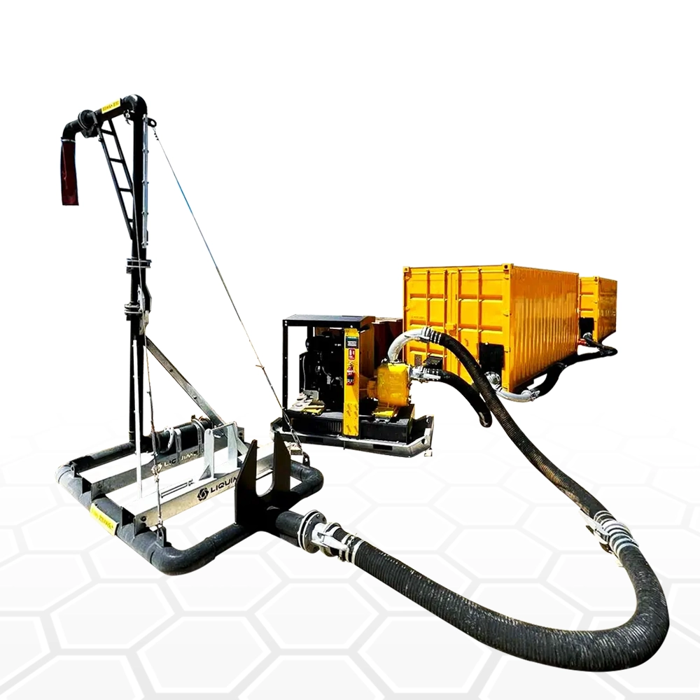
This is why the complete liquid management system should be considered as one engineered package.
Integrating Pumps, Storage and Pipework
A centrifugal pump is only one part of a liquid management system.
A complete system may include:
- Bulk storage tanks
- Centrifugal pumps
- Suction pipework
- Discharge pipework
- Footvalves
- Strainers
- Isolation valves
- Flow-control equipment
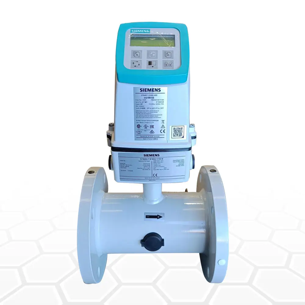
- Instrumentation
- Control panels
- Telemetry
- Standpipes
- Safety systems
- Structural frames and access systems
Each component affects the performance of the others.
For example, increasing the pump flow rate without reviewing the suction pipe diameter may increase suction losses and cavitation risk. Similarly, installing a highly restrictive strainer can reduce the available suction pressure and limit pump performance.
The system therefore needs to be designed around the required operating point.
Water Truck Filling and Standpipe Applications
High-flow water truck filling is a common application where pump and standpipe design must work together.
The objective is not simply to install the largest available pump. The system must deliver the required flow at the required pressure while maintaining acceptable hydraulic losses.
The design should consider:
- Tank volume
- Required fill time
- Target flow rate
- Static elevation
- Pipe diameter
- Hose length
- Standpipe configuration
- Pump head
- Pump efficiency
- Available power
- Valve configuration
- Water hammer risk
- Operator safety
For example, a 25,000-litre tanker requiring a five-minute fill requires an average flow of approximately 5,000 L/min. The pump and hydraulic system must then be sized to achieve that flow under the actual site conditions.
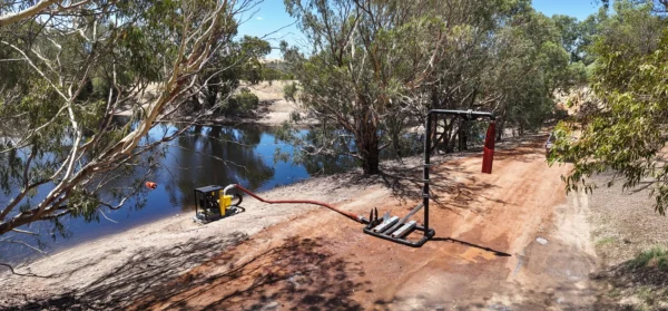
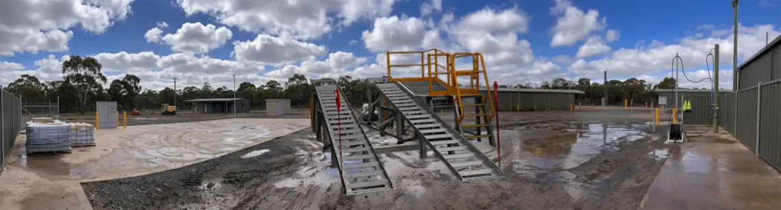
Liquimech develops engineered pump and standpipe solutions designed around the required flow, storage configuration and site conditions.
Dewatering Applications
Dewatering requirements vary significantly between sites.
A system may need to remove:
- Groundwater
- Stormwater
- Pit water
- Construction water
- Sediment-laden water
- Water containing suspended solids
Pump selection should account for the characteristics of the water and the consequences of pump failure.
For critical dewatering applications, the system may also require:
- Standby capacity
- Automatic controls
- Level monitoring
- Remote monitoring
- Redundant pumps
- Robust suction protection
- Accessible maintenance points
The correct solution depends on the consequences of water accumulation as well as the required pumping rate.
Reducing Total Cost of Ownership
The lowest purchase price does not necessarily produce the lowest cost over the life of a pump. A properly sized pump can reduce energy consumption and mechanical stress. Appropriate materials can increase component life. Good access to serviceable components can reduce maintenance time.
For remote sites, these factors can have a particularly large impact because maintenance and equipment transport can be significantly more difficult.
How Liquimech Approaches Industrial Pump Systems
Liquimech takes a system-level approach to industrial liquid management.
Rather than treating a centrifugal pump as a standalone piece of equipment, Liquimech considers how the pump interacts with storage, suction pipework, discharge systems, valves, controls, standpipes and site operating conditions.
This approach allows the pump package to be engineered around the actual duty rather than selected from a single flow-rate requirement.
Liquimech solutions can be engineered around applications including:
- Mining dewatering
- Industrial water transfer
- Civil construction
- High-flow water truck filling
- Bulk liquid transfer
- Remote pumping
- Storage and transfer systems
- Custom liquid management infrastructure
Engineered Pump Packages
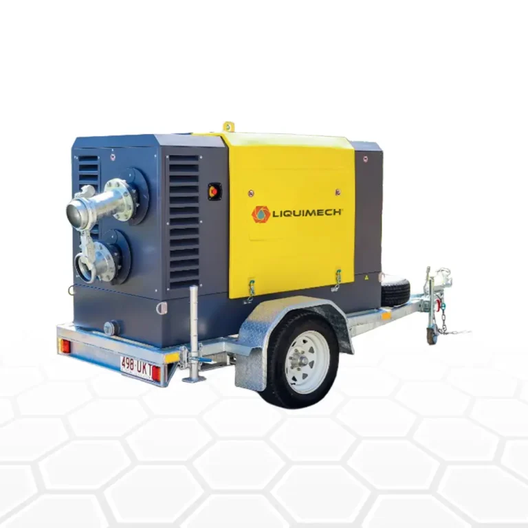
Liquimech can develop complete pump packages around the requirements of the project.
Depending on the application, a system can incorporate:
- Pump and driver
- Structural frames
- Valves
- Strainers
- Footvalves
- Pipework
- Instrumentation
- Control systems
- Telemetry
- Standpipes
- Storage integration
The objective is to provide a system that is practical to install, operate and maintain in the field.
Designed for Australian Operating Conditions
Australian mining, civil and industrial projects can involve harsh operating environments and remote locations.
Liquimech designs systems with these conditions in mind, focusing on:
- Equipment reliability
- Serviceability
- Hydraulic performance
- Appropriate materials
- Site safety
- Ease of installation
- Maintenance access
- Long-term operating cost
The result is a liquid management system designed around the project rather than a collection of disconnected components.
Centrifugal Pump Selection Checklist
Before specifying a centrifugal pump, confirm the following:
Hydraulic requirements
- What flow rate is required?
- What is the total dynamic head?
- What is the static lift?
- What are the pipe and hose friction losses?
- What pressure is required at the discharge point?
- Where is the intended operating point relative to BEP?
Fluid requirements
- What liquid is being pumped?
- What is its temperature?
- What is its viscosity?
- What is its density?
- Does it contain solids?
- What is the particle size?
- Is the fluid abrasive?
- Is the fluid corrosive?
- What materials are chemically compatible?
Suction requirements
- What is the available liquid level?
- What is the suction lift?
- What is the NPSHa?
- What is the pump’s NPSHr?
- Is the suction pipe adequately sized?
- Is a footvalve required?
- Is a strainer required?
- Can the suction system introduce air?
Installation requirements
- Is the foundation adequate?
- Can the pump and driver be aligned correctly?
- Is the pipework independently supported?
- Is the pump accessible for maintenance?
- Is the power source suitable?
- Is the pump protected from environmental conditions?
Operational requirements
- How many hours will the pump operate?
- Is the duty continuous or intermittent?
- Can the pump run dry?
- Can the discharge valve close?
- Is standby capacity required?
- Is remote monitoring required?
- How quickly must maintenance be completed?
Frequently Asked Questions
What is a centrifugal pump used for?
A centrifugal pump is primarily used to transfer relatively low-viscosity liquids at moderate to high flow rates. Common industrial applications include dewatering, water transfer, tank filling, process water, dust suppression and water truck filling.
How do I choose a centrifugal pump?
Select a centrifugal pump based on the required flow rate and total dynamic head, then verify the fluid properties, solids content, temperature, suction conditions, NPSH, materials, power source and operating duty. The pump should be selected using its performance curve rather than flow rate alone.
What is NPSHa?
NPSHa is Net Positive Suction Head Available. It represents the suction pressure available to the pump under the actual system operating conditions. NPSHa must provide sufficient margin above the pump’s NPSHr to reduce the risk of cavitation.
What is NPSHr?
NPSHr is Net Positive Suction Head Required. It is the suction head requirement specified for the pump at a particular operating condition. It is obtained from the pump’s performance data.
What causes centrifugal pump cavitation?
Cavitation occurs when pressure at the pump suction or within the pump falls sufficiently for vapour bubbles to form and subsequently collapse. Causes can include excessive suction lift, undersized suction pipework, blocked strainers, excessive flow, high liquid temperature or inadequate NPSH margin.
Can centrifugal pumps handle solids?
Some centrifugal pumps can handle liquids containing solids, particularly when fitted with suitable open or semi-open impellers and wear-resistant components. The correct pump depends on the solids concentration, particle size, abrasiveness and required operating conditions.
What is the difference between an open and closed impeller?
A closed impeller has shrouds around its vanes and generally provides higher hydraulic efficiency for cleaner liquids. An open impeller has exposed vanes and can provide better solids-handling capability, although it may have different efficiency and wear characteristics.
Can a centrifugal pump run dry?
A conventional centrifugal pump should not be allowed to run dry unless it has been specifically designed for dry-running conditions. Dry operation can rapidly damage mechanical seals and other components.
Why is my centrifugal pump vibrating?
Common causes include cavitation, shaft misalignment, an unbalanced impeller, bearing problems, pipework loads, foundation issues or operation outside the pump’s preferred operating range. Vibration should be investigated promptly because continued operation can cause secondary damage.
What happens if a centrifugal pump runs against a closed valve?
A centrifugal pump operating against a closed discharge valve has little or no flow through the system. Energy continues to be transferred into the liquid inside the pump, which can cause overheating and damage if the condition continues. The pump should be operated within its specified minimum-flow limits.
How do I calculate water truck filling flow rate?
Divide the required tank volume by the target fill time.
For example:
25,000 litres ÷ 5 minutes = 5,000 L/min
The pump must then be capable of delivering that flow at the total dynamic head of the actual pipework and standpipe system.
How often should a centrifugal pump mechanical seal be replaced?
There is no universal replacement interval. Seal life depends on the fluid, temperature, pressure, solids, shaft condition, alignment, installation quality and operating conditions. A condition-based maintenance approach is generally more effective than replacing every seal at an arbitrary interval.
How can centrifugal pump downtime be reduced?
Start with correct hydraulic sizing and material selection. Then focus on proper installation, suction-side protection, alignment, lubrication, condition monitoring and preventive maintenance. On remote sites, designing for serviceability and access to critical components is equally important.
Does Liquimech provide complete pump systems?
Yes. Liquimech engineers complete liquid management systems around the project’s hydraulic, mechanical and operational requirements. Solutions can integrate pumps with storage, pipework, valves, footvalves, strainers, standpipes, controls and monitoring systems.
How to Select the Right Centrifugal Pump System for Your Project?
A reliable centrifugal pump system starts with correct engineering, not simply the selection of a pump with a high flow rating.
The pump must be matched to the hydraulic duty, fluid characteristics, suction conditions, materials, operating environment and maintenance requirements. NPSH, total dynamic head, pump efficiency, impeller configuration and suction-side design all have a direct effect on reliability.
For Australian mining, civil and industrial projects, the surrounding infrastructure is equally important. Storage, pipework, valves, strainers, footvalves, controls and monitoring systems must work together as one liquid management system.
Liquimech applies this system-level approach to engineered pump and liquid management solutions, helping Australian projects improve hydraulic performance, reliability, maintainability and long-term operating efficiency.
If your project requires a centrifugal pump system for dewatering, water transfer, truck filling or another high-flow industrial application, Liquimech can engineer the system around the actual site requirements.